The Amroh MK telemax was a device that you could build yourself somewhere in the mid-fifties. A television is a complex device and many people are afraid of the high voltage. So it's something you don't find quickly but you can build yourself. What I personally think is that the circuit of the telemax is not well put together and it concerns the vertical part. And I changed that part so that it works perfectly all of a sudden.

The chassis is made and now the first tube is mounted on the chassis.

Accurately placing a picture tube in the center requires some precision.

When the picture tube is installed you need a power supply and a line oscillator and high voltage generator.

So I'll start with the line oscillator. This circuit can also operate on a separate power supply.

And see here the first life of the line oscillator.

We start with a loose setup to see if everything will work.

The power supply is required to operate the line output stage.

The line oscillator works but not quite right.

In this mess setup the high voltage is 10Kv.

Here's a better view of the meter.

The line oscillator now works properly.

But still 10Kv.

It does give light in the picture tube.

It can also give a little more light.

But in the end the high voltage works.

In the end it might work with this setup.

Time to mount everything. The underside looks like this.

The line transformer mounted on the chassis.

And here's a close look.

And luckily everything still works after this renovation.

Just mounted the chassis in the trestle.

And then it's time for vertical deflection.

Because the Amroh circuit does not work, I thought to use the Philips circuit for this.

And as you can see here, that doesn't work either. but we have a small grid.

The grid circuit on the underside of the chassis.

The image is still too small.

An adjustment and....

Beautiful grid sawtooth impulse.

And look what a beautiful grid on the picture tube.

Time for images on the picture tube. in the top left corner is the video amplifier. We are going to make a modification to the grid synchronization.

But first image from the video amplifier.

Sometimes it is useful to have a place where you can store the solder tin.

The sync separator. Here the horizontal pulse.

And here's the vertical sync pulse.

The image without synchronization.

Here the vertical sync pulse separated from the horizontal sync pulse this is the modification I made up for the Amroh Telemax.

And here's the extra tube they forgot to draw. And why this concept does not work well.

The image with only vertical synchronization, the rest was not important for a while.

And here around a corner I took a picture of the total synchronization.

Here you can see the vertical synchronization amplifier tube hanging on some Chinese wires at the bottom right.

Now we are going to mount the loose tube on the chassis.

On the left side of the small tube is the synchronization separator, next to it comes our vertical sync pulse amplifier.

After placing the tube on the chassis for a test, everything still seems to work.

And see here the tube is neatly mounted on the chassis, modification successful.

And this is what the image looks like.

Just a side view.

Measurements on the contrast control.

We use the line recoil impulse to trigger the scope.

Low contrast.

Just a loos test.

The chassis and the video circuit.

The image at half contrast.

The video signal at half contrast.

The image at minimum contrast.

The video signal at minus contrast.

The image at max contrast.

The video signal at max contrast.

The test setup. As always a lot of loose measuring leads.

The reception part here we built the channel 4 receiver and the image mf.

Video definition passing is a drama, so to speak.

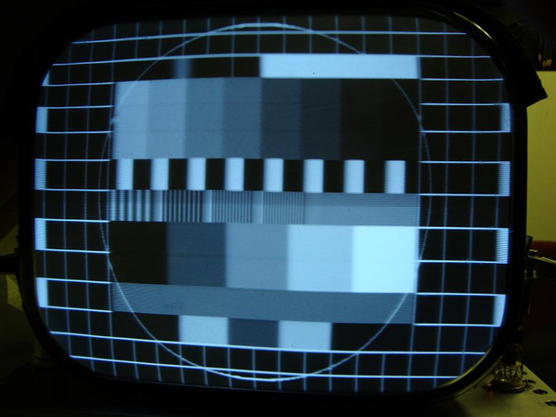
The definition image seems OK.

The test image from the receiver.

The video signal of the test pattern from the receiver.

The receiver part under the chassis.

The receiving part above side chassis. note sound is not built yet.

Just a test with some moving image.

With a lot of tinkering, the image is reasonably no more than that.

The video signal remains a drama.

Some more images to finish it off.

An old acquaintance.

Sound also seems to be important.

So sound mf built.

Measurements on the sound part here the 5.5Mhz carrier wave.

Sound carrier wave on red LED on the right.

No sound carrier.

Sound carrier off.

Sound carrier on and modulated with 1Khz.

Modulated sound carrier wave.

The sound detector coil.

The sound detector circuit.

Sound.

The Chassis.

The receiver part.

The last things.

The image.

The chassis.

Rex.
Sound and Vision. Building a Television is a complex affair. The given circuits are often limited by patents, etc. So as a builder you have to be creative to make such a device work properly.